 Get in touch
 English
 Deutsch
 中文简体
 Español


1. Introduction: Deconstructing AC Induction Motor Horsepower The AC Induction Motor is one of the m...
READ MOREIndustry News
2026-11-17
Content
A 24 V brushless motor rated at 300 W can still overheat inside a sealed handheld tool housing when the drive's current limit sits above the winding's continuous thermal rating. The motor is rarely the whole problem, and it is never the whole answer.
A brushless motor system is the complete assembly that turns a DC bus into controlled shaft torque: a three-phase stator, a permanent-magnet rotor, the commutation electronics, the position feedback source, and the mechanical and thermal path that binds them together. Specify the motor alone and the other four elements still get chosen, just not by the person holding the thermal model.
Working definition
A brushless motor system is a closed loop of electrical input, electronic commutation, magnetic torque production and heat removal. A gain in one element is always paid for somewhere else in the loop.
A brushless motor system consists of five specified parts, and any part left undefined becomes a default chosen later in the supply chain.
The drive is the element most often separated from the motor, and that separation carries a real cost: long motor leads add inductance, switching losses and radiated noise. A brushless DC motor with an integrated controller shortens the loop to a few centimetres and removes a connector from the assembly bill of materials.
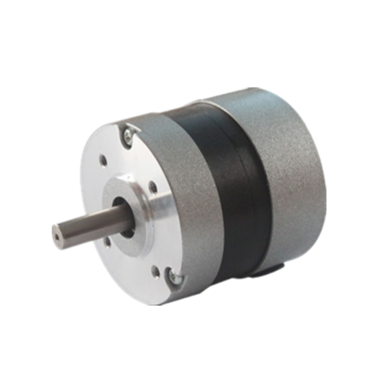
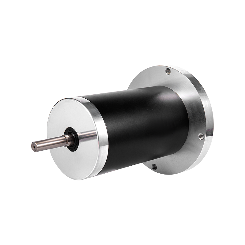
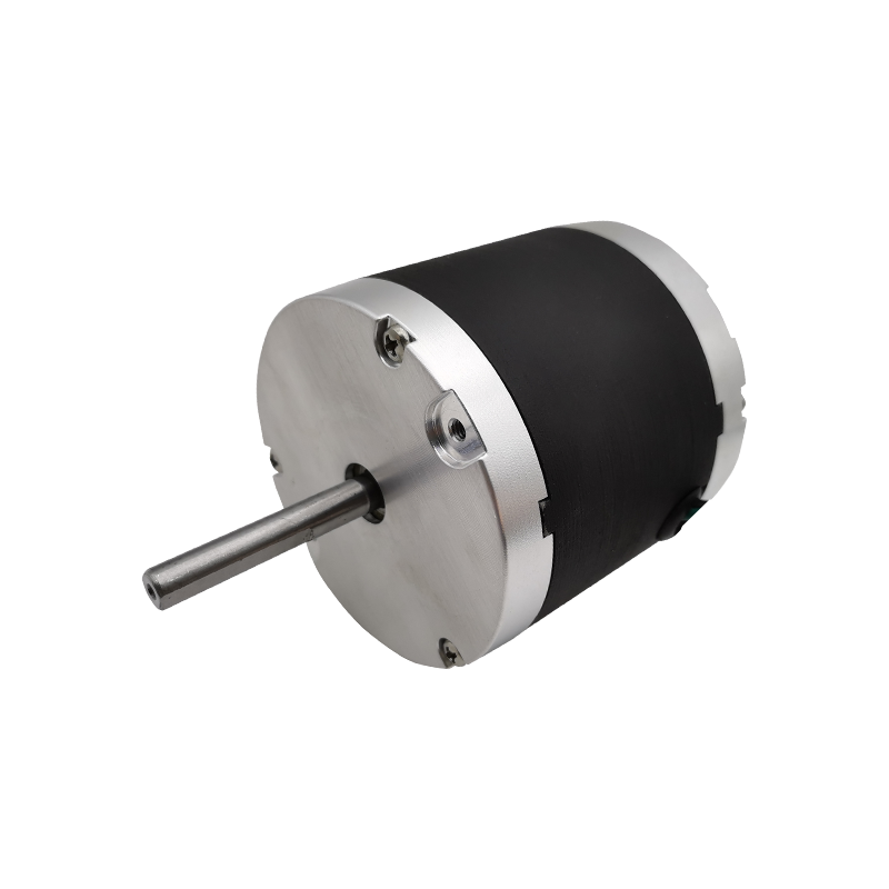 BL80 Series 80 mm Diameter Brushless DC MotorAn 80 mm brushless motor for industrial high-load use, with high torque and efficiency; worth reviewing when the drive-to-motor path and connector count matter.View Product →
Six-step commutation with three Hall sensors is the lowest-cost way to run a BLDC, while sinusoidal field-oriented control with position feedback buys smoother torque at low speed at the price of a sensor harness and tuning time.
Neither choice is inherently better. The load makes the decision: a fan or a centrifugal pump with a predictable quadratic torque curve tolerates sensorless six-step control, while a robot joint that must hold position at zero speed does not.
| Feedback source | Angular information | Strength | Constraint |
| Three Hall sensors | 60 electrical degrees | Works from zero speed at low cost | Torque ripple at each commutation step |
| Sensorless back-EMF | Estimated from phase voltage | No harness, no sensor cost | Needs a minimum speed before the estimate is valid |
| Incremental encoder | 1,000 to 4,000 counts per revolution | Fine velocity control and closed-loop position | Homing routine required at every power-up |
| Absolute encoder | Unique position at power-up | No homing, immediate servo lock | Highest cost and the largest cable diameter |
Commutation decides how the torque is produced. Feedback decides how precisely that torque can be repeated.
Cogging torque is the periodic variation produced by the interaction between rotor magnets and stator teeth, and it is fixed by slot-and-pole geometry and magnet shaping rather than by the drive.
A 12-slot, 10-pole combination with concentrated windings gives a short magnetic period and modest cogging. A 9-slot, 8-pole combination pushes the cogging frequency higher still, which matters when the load is a direct-drive gimbal, a medical drill or a personal care appliance where the disturbance becomes visible jitter or an audible tone.
Retek Motion builds a family of low-cogging brushless DC motors aimed at exactly this problem, with winding layout and magnet geometry chosen to spread the cogging harmonic across a wider frequency band so it stops exciting a structural resonance in the housing.
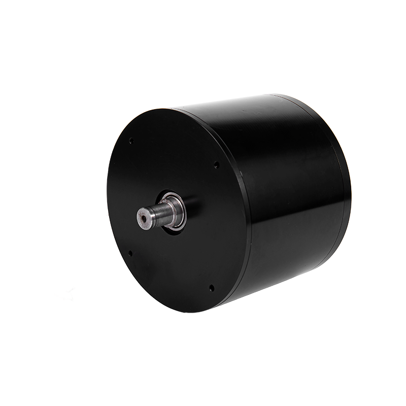 BL112 112 mm Low-Cogging Brushless DC MotorA 24 VDC, 600 W low-cogging brushless motor for smooth, low-vibration CNC and robotics use, where reduced cogging noise and precision matter.View Product →
Continuous torque is a thermal rating, not a magnetic one. A motor that produces 3 N·m for ten seconds may be limited to 1 N·m indefinitely in the same housing, and the gap between those two numbers is the whole design.
The limiting component is whichever part reaches its ceiling first. Winding insulation, magnet grade, bearing grease and the drive's MOSFET junction all have separate limits, and they rarely peak at the same operating point. Bearing grease life roughly halves for every 10 K rise above its rated temperature, so the winding is often not the first part to fail in a hot enclosure.
Practical rule
Measure winding temperature at maximum ambient with the real housing and the real cable length. A bench run in open air understates the rise by a margin large enough to invalidate the rating.
Efficiency in a brushless motor system peaks in a narrow band around 60 to 80 percent of rated torque and falls away at both ends, because copper loss rises with the square of current while iron and windage loss rise with speed.
Minimum full-load efficiency, IEC 60034-30-1, 4-pole, 1.1 kW, 50 Hz (bars scaled from 80 to 95 percent)
The IEC 60034-30-1 efficiency classes apply to line-fed induction machines, yet they remain a useful benchmark for any variable-speed drive project: IE4 at 1.1 kW and four poles requires 91.1 percent full-load efficiency, and a brushless system that cannot clear that bar at the design point usually has a winding or drive loss problem rather than a magnet problem.
Copper loss scales as I squared R, so a 20 percent current overload adds 44 percent to the resistive heat. That single relationship explains why a current limit set from peak torque rather than continuous torque is the most common cause of premature winding failure in battery-powered equipment.
A production-ready specification fixes six parameters before an RFQ goes out: bus voltage, continuous and peak torque, duty cycle, maximum ambient temperature, feedback type and enclosure rating.
Jiangsu Retek Motion Co., Ltd., operating from Suzhou as Suzhou Retek Electronic Technology Co., Ltd., has designed and manufactured brushless DC motors in-house since 2018 and brought cable overmolding and CNC machining inside the same facility in 2021. The company reports shipping to more than 20 countries by 2024, and its engineering team draws on more than 25 years of motor development experience across brushed, brushless and coreless platforms.
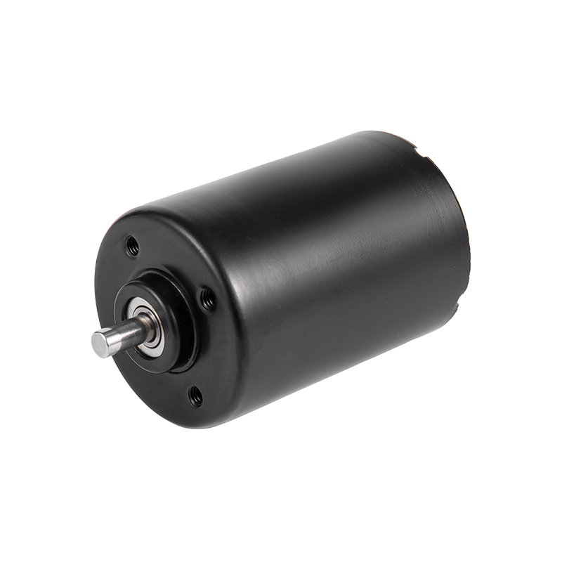 W42 42 mm Brushless DC Motor for Robotic Lawn MowersA 42 mm brushless motor for robotic lawn mowers, suited to outdoor use, low-power efficiency and minimal maintenance; consider it alongside drive and thermal requirements.View Product →
A brushless motor is the stator, rotor and bearings. A brushless motor system adds the commutation drive, the feedback source and the thermal path, and those three elements move the continuous rating more than the magnetics do. The same 57 mm motor can carry different continuous torque depending on how the drive limits current and how the housing removes heat.
Sensorless back-EMF estimation works when the load never demands full torque at or near standstill. Fans, pumps, propeller loads and centrifugal blowers qualify because their torque demand falls away at low speed. Indexing tables, robot joints and anything that must hold position under load do not, and a Hall sensor set or an encoder is the cheaper answer over the life of the product.
Six items make an RFQ actionable: bus voltage with tolerance, continuous and peak torque with the duty cycle that produces them, maximum ambient temperature, feedback type, enclosure rating and annual volume. Adding a torque-speed curve and a target service life removes the first design iteration entirely, which is why Retek Motion starts every project from a specification rather than a catalogue number.
Run three checks. First, a thermal soak at maximum ambient inside the production housing with the final cable length. Second, an endurance run at rated load long enough to expose bearing and brushless drive wear, typically 1,000 hours. Third, an EMC scan of the motor cable, because the switching edge of the drive is the emission source and the cable is the antenna.
1. Introduction: Deconstructing AC Induction Motor Horsepower The AC Induction Motor is one of the m...
READ MORE1. Introduction In modern industrial automation, data center construction, consumer electronics upgr...
READ MOREStepper motors represent a cornerstone of modern motion control, offering precise positioning and re...
READ MOREThe industrial motor landscape is undergoing a significant transformation, driven by the relentless ...
READ MORERelated Products
Building 10, No.199, Jinfeng Road, Suzhou High-tech, Jiangsu Province, China
+86-133 3869 4967
+86-512 6876 9967
sean@retekmotion.com
rsgrivic@126.com
 WhatsApp
Copyright © Jiangsu Retek Motion Co., Ltd. All Rights Reserved. Custom OEM Industrial Multi Rotor Drone Motors Manufacturers