 Get in touch
 English
 Deutsch
 中文简体
 Español


1. Introduction: Deconstructing AC Induction Motor Horsepower The AC Induction Motor is one of the m...
READ MOREIndustry News
2026-11-10
Content
A brushless motor is a permanent-magnet synchronous machine whose stator windings are switched by an electronic drive instead of a mechanical commutator, so the only parts that touch are the bearings.
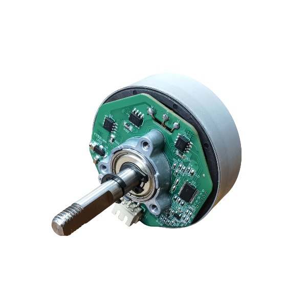
The parts count inside the housing is lower than most first-time buyers expect. A laminated stator carries three-phase windings; the rotor carries surface-mounted or interior permanent magnets; two bearings locate the shaft; and on sensored versions three Hall-effect latches sit 120 electrical degrees apart. The copper-on-carbon sliding contact that wears out a brushed motor is gone, and with it the brush dust, the commutator film and the re-tensioning that go with them.
The trade is straightforward: the drive becomes part of the motor specification. Commutation timing, current limit, the speed loop and, on integrated units, the fieldbus interface all sit in the electronics. A winding that is correct on a six-step drive can be wrong on a field-oriented one, because the two assume different back-EMF shapes and different current waveforms.
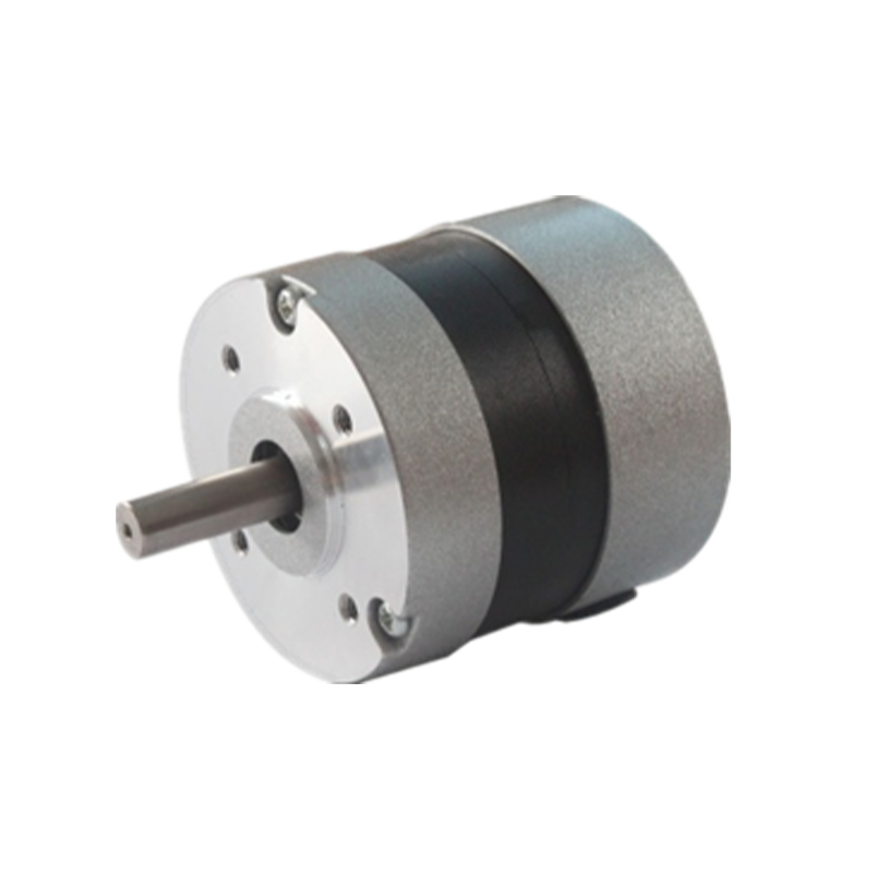 BL57 57 mm Brushless DC MotorA 57 mm brushless DC motor offered for OEM/ODM customization, relevant when matching winding and drive electronics to commutation choices.View Product →
Six-step commutation switches two of the three phases at a time and is the cheapest way to spin a brushless motor; field-oriented control resolves stator current into torque and flux components and pulls torque ripple down from roughly 10 to 15 percent of rated torque to 3 to 5 percent.
Trapezoidal designs are built for six-step drives. The back-EMF is flat-topped over 120 electrical degrees, so current can be blocked in the same window and the product of the two stays nearly constant. Sinusoidal designs are built for FOC, which needs a continuous position estimate and a current loop fast enough to track it. Mixing the two is where most prototype noise comes from.
Electrical frequency, not mechanical speed, is what the drive has to track. A 4-pole-pair motor at 4,000 rpm sees 267 Hz; a 14-pole-pair outrunner at the same shaft speed sees 933 Hz. At a 20 kHz PWM carrier the current loop only gets about 21 switching periods per electrical cycle at the high end, which is why high pole counts and low-inductance windings push drives toward faster processors or lower carrier frequencies.
In SI units the back-EMF constant and the torque constant are numerically identical. A motor with 0.05 V per radian per second of back-EMF returns 0.05 N.m per amp of quadrature current. That single number ties bus voltage to top speed and current to torque, and it is the first thing to check when a sample runs too fast or stalls too early.
| Method | Rotor feedback | Torque ripple | Drive cost | Typical fit |
| Six-step trapezoidal | Three Hall latches or sensorless back-EMF | 10 to 15 percent | Lowest | Pumps, fans, power tools |
| Sinusoidal FOC | Hall latches, encoder or observer | 3 to 5 percent | Moderate | Medical drives, robotics, quiet HVAC |
| Sensorless FOC | Back-EMF observer above roughly 10 percent speed | 3 to 5 percent | Moderate | Compressors, drone propulsion, blowers |
A brushless motor wins whenever the duty cycle is long, the housing is sealed, or the load needs torque at low speed; a brushed motor with replaceable brushes still wins on drive cost and on projects where extra electronics cannot be qualified in time.
Brush life decides most of these arguments. A 40 mm to 52 mm brushed motor with replaceable carbon brushes typically carries a rated brush life in the 1,000 to 3,000 hour range, and that figure assumes clean air, moderate ambient and no sustained low-speed running. A brushless motor of the same frame has no wear item at that interface, so the limiting factors move to bearing grease life and the electrolytic capacitors inside the drive.
Continuous torque at the operating speed sets the frame size; every other number in the datasheet is a consequence of that pair plus the duty cycle.
| Parameter | What it fixes | Value to confirm |
| Continuous torque | Frame size and winding | N.m at the duty-point speed, 20 percent margin |
| Bus voltage | Turns count and back-EMF constant | 24 V nominal with a 20 to 28 V window |
| Duty cycle | Thermal margin | Continuous, 25 percent ED, or 10 minute peak |
| Ambient and IP | Insulation class and sealing | 40 C ambient, IP54 or IP65 |
| Load inertia | Acceleration current limit | Ratio below 5:1 |
| Feedback | Drive interface and cable count | Hall, encoder or sensorless |
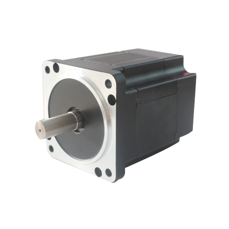
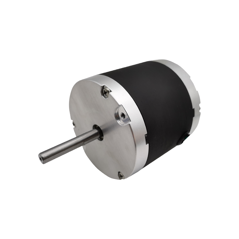 BL80 series 80mm Diameter Brushless DC MotorProduct Definition: The BL80 series is an 80mm diameter brushless DC motor, designed for high-load applications. It features powerful power output and high torque capa...View Product →
Bearing current, low-speed overheating and drive-side overvoltage from regenerative braking account for more brushless failures in the field than magnet or winding defects.
Off-the-shelf brushless motors cover the common 24 V and 3,000 rpm duty points; the moment the requirement includes a non-standard shaft, an IP65 seal or a specific connector, the winding and the mechanical interface are usually customized rather than the machine redesigned around a catalog part.
Two families carry most of that work. Low-cogging designs use slot and pole combinations that suppress detent torque, which matters when an encoder resolves a few arc minutes and the load is a lens or a syringe. Integrated-controller units move the inverter into the rear cap, which removes a cabinet, shortens the motor cable and eliminates the reflected-wave problem entirely.
Both routes need the same input from the buyer: a torque-speed point, a duty cycle, a bus voltage, an ambient and a mounting drawing. Suppliers that also machine housings and assemble harnesses in house can hold the tolerance stack from stator bore to connector keyway in one drawing set, which is where most customization projects lose time.
For a low-detent design, review the low-cogging brushless DC motor range; for a sealed package with the electronics on board, start with the brushless DC motors with integrated controller.
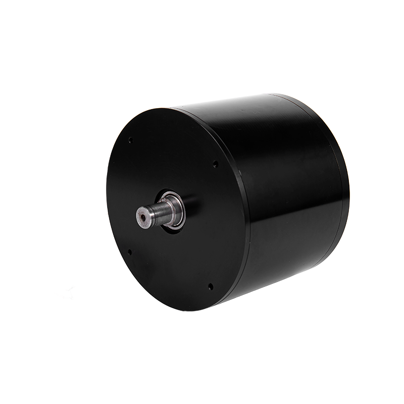 BL112 Low-Cogging 112 mm Brushless DC MotorA 112 mm low-cogging brushless DC motor rated 24 VDC and 600 W, suited to precision CNC and robotics applications needing smooth, low-vibration operation.View Product →
Start from continuous torque at the duty-point speed and add 20 percent. Then pick a back-EMF constant so the motor reaches top speed at no more than 85 percent of the minimum bus voltage, which on a 24 V nominal rail is about 20.4 V. With 0.05 V per radian per second, that caps speed near 400 rad/s, or 3,800 rpm.
No. Back-EMF is zero at standstill, so a sensorless drive must ramp the motor open-loop until the observer locks, typically above 10 percent of rated speed. For full torque at zero speed, specify three Hall latches or an incremental encoder.
IP65 to IEC 60529 covers dust-tight enclosures with low-pressure water jets from any direction, which suits food-processing and medical cleaning. IP67 adds short immersion. In both cases the shaft seal and the cable gland are the first components to be qualified, not the housing.
Yes, when the axis moves slowly or the encoder resolves below one arc minute. Cogging is typically 1 to 5 percent of rated torque in a standard 12-slot, 8-pole design, and a low-cogging slot and pole combination reduces it without changing the drive or the frame size.
1. Introduction: Deconstructing AC Induction Motor Horsepower The AC Induction Motor is one of the m...
READ MORE1. Introduction In modern industrial automation, data center construction, consumer electronics upgr...
READ MOREStepper motors represent a cornerstone of modern motion control, offering precise positioning and re...
READ MOREThe industrial motor landscape is undergoing a significant transformation, driven by the relentless ...
READ MORERelated Products
Building 10, No.199, Jinfeng Road, Suzhou High-tech, Jiangsu Province, China
+86-133 3869 4967
+86-512 6876 9967
sean@retekmotion.com
rsgrivic@126.com
 WhatsApp
Copyright © Jiangsu Retek Motion Co., Ltd. All Rights Reserved. Custom OEM Industrial Multi Rotor Drone Motors Manufacturers