 Get in touch
 English
 Deutsch
 中文简体
中文简体 Español
1. Introduction: Deconstructing AC Induction Motor Horsepower The AC Induction Motor is one of the m...
READ MOREIndustry News
2026-04-21
Content
A DC (direct current) motor converts electrical energy into mechanical rotation using the interaction between a magnetic field and a current-carrying conductor. The operating principle follows from the Lorentz force law: when electric current flows through a conductor placed inside a magnetic field, the conductor experiences a force perpendicular to both the current direction and the field direction. Arrange enough current-carrying conductors in a rotating assembly and that force becomes continuous rotational torque.
In practical terms, a DC motor contains two fundamental magnetic systems. The stator provides a stationary magnetic field — either from permanent magnets or electromagnets (field windings). The rotor (also called the armature) carries conductors connected to an external DC power supply. Current flowing through the rotor conductors reacts with the stator field to generate torque, spinning the rotor. As long as DC voltage is applied, the motor continues to rotate.
Speed in a DC motor is primarily controlled by the applied voltage: higher voltage produces faster rotation. Torque output is proportional to armature current. This straightforward relationship between voltage, current, speed, and torque makes DC motors exceptionally easy to control across a wide operating range — a property that explains their continued dominance in variable-speed drive applications.
The internal architecture of a DC motor varies between brushed and brushless designs, but several core components are common across both types.
The stator is the stationary outer assembly of the motor. In small and fractional-horsepower DC motors, the stator field is produced by permanent magnets fixed to the inner bore of the motor housing. In larger industrial DC motors, the stator carries field windings — coils of wire wound around pole pieces — through which a separate DC excitation current flows to create the magnetic field. The stator frame is typically laminated silicon steel to minimize eddy current losses.
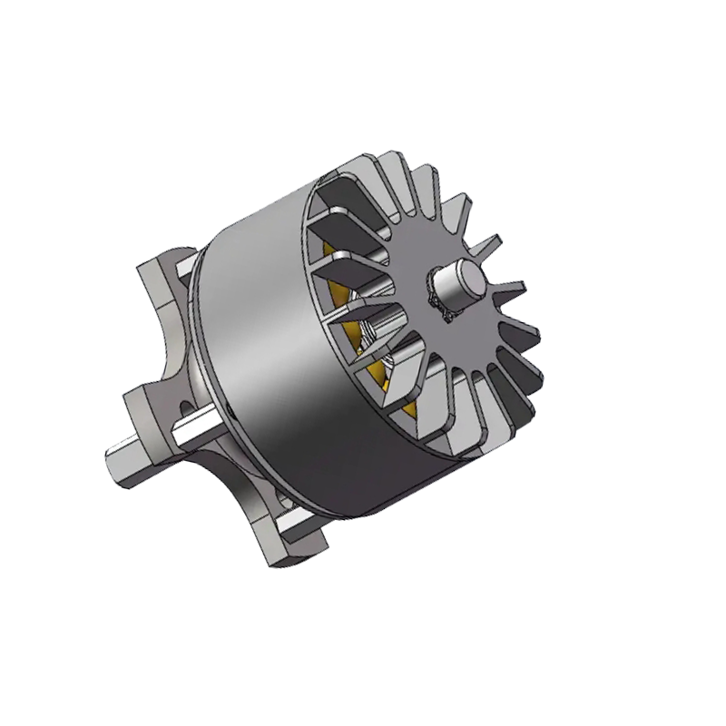
The rotor is the rotating assembly mounted on the motor shaft. It consists of a laminated iron core with slots machined around its circumference, into which the armature windings are wound. The laminated construction reduces eddy current losses in the iron. In brushed DC motors the rotor carries the wound coils; in brushless DC motors the rotor carries the permanent magnets instead.
The commutator is a segmented copper ring mounted on the rotor shaft. Each segment connects to a different armature coil. Carbon brushes — spring-loaded contacts mounted in the stator housing — press against the commutator surface and maintain electrical contact as the shaft rotates. As the rotor turns, the commutator segments pass under the brushes in sequence, automatically switching the current direction in each coil at the right moment to keep the torque acting in a consistent rotational direction. This mechanical switching is what defines a brushed DC motor.
Armature windings are insulated copper conductors wound into the rotor slots. The winding configuration — lap, wave, or simplex — determines the number of parallel current paths through the armature and affects the motor's speed-torque characteristics. Field windings on the stator, when present, are wound to produce the correct number of magnetic poles for the design speed and torque range.
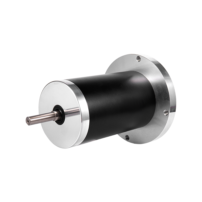
The output shaft transmits mechanical torque to the load. Precision ball bearings or sleeve bearings support the shaft at each end of the housing, maintaining the air gap between rotor and stator within tight tolerances. The housing (end bells and frame) provides structural support, protects internal components, and in some designs incorporates cooling fins or mounting provisions for an external fan.
In a brushed direct current motor, the commutator and brushes perform the current-switching function mechanically. As the armature rotates, the commutator segments move past the stationary brush contacts, connecting each armature coil to the supply in sequence. This ensures that regardless of rotor position, the coil currently aligned with the stator pole gap always carries current in the correct direction to produce forward torque.
The result is a motor that runs directly from a DC supply with no external electronic commutation required. Connect a brushed DC motor to a battery or regulated DC supply and it rotates immediately. Reverse the polarity and it reverses direction. This simplicity is the primary reason brushed motors remain widely used in cost-sensitive, low-to-medium complexity applications.
The mechanical contact between brushes and commutator introduces the motor's key limitations. Brush-commutator friction generates heat and wear debris, and the arcing that occurs as segments switch produces electromagnetic interference (EMI). Brush replacement is typically required every 1,000–5,000 operating hours depending on current load, speed, and operating environment. The commutator surface also requires periodic inspection and resurfacing.
Brushed DC motors are not suitable for use in flammable or explosive atmospheres because brush arcing can ignite surrounding gases. They are also limited in maximum speed by the mechanical constraints of the brush-commutator contact, typically topping out at 3,000–8,000 RPM in most designs.
A brushless DC motor (BLDC) eliminates the commutator and brush assembly entirely by relocating the permanent magnets to the rotor and the windings to the stator. Current switching — commutation — is handled electronically by a motor controller that monitors rotor position through Hall effect sensors or back-EMF detection and energizes the stator coils in the correct sequence to sustain rotation.
This architectural inversion has significant consequences for performance, maintenance, and application range.
| Characteristic | Brushed DC Motor | Brushless DC Motor |
|---|---|---|
| Commutation method | Mechanical (brushes + commutator) | Electronic (controller + sensors) |
| Efficiency | 75–85% | 85–95% |
| Maintenance | Regular brush replacement required | Minimal — bearings only |
| Speed range | Up to ~8,000 RPM typical | Up to 100,000+ RPM possible |
| EMI / arcing | Significant brush arcing | Low (no brush contact) |
| Hazardous environment suitability | Not suitable (brush arcing) | Suitable (no arcing) |
| Controller requirement | Simple DC voltage control | Dedicated electronic controller required |
| Unit cost | Lower | Higher (motor + controller) |
| Lifespan | Limited by brush wear | Longer — no wearing contact parts |
The efficiency advantage of brushless motors is particularly significant in battery-powered applications. An electric vehicle drivetrain or power tool running a BLDC motor at 92% efficiency versus a brushed equivalent at 80% translates directly into longer run time per charge and reduced thermal load on the battery pack. This is the primary driver behind the near-universal shift to brushless motors in cordless power tools, electric vehicles, drones, and HVAC systems over the past two decades.
Despite the performance advantages of brushless designs, brushed DC motors remain the correct choice in several application categories.
A DC motor drive (also called a DC drive or DC controller) is the power electronics package that regulates the voltage and current supplied to a DC motor to control its speed, torque, acceleration, and direction. The motor and drive together form a complete motion control system — the motor provides mechanical output, and the drive manages electrical input to achieve the desired motion profile.
Traditional brushed DC drives use thyristor (SCR) phase-control or PWM (pulse-width modulation) techniques to regulate armature voltage. A four-quadrant drive can control speed and torque in both rotational directions, enabling regenerative braking — where the motor acts as a generator during deceleration, returning energy to the supply bus. This capability is widely used in industrial applications such as winding machines, rolling mills, and hoists where controlled deceleration and energy recovery matter.
The speed regulation accuracy of a closed-loop brushed DC drive with a tachometer feedback signal is typically ±0.1% of set speed, which explains their long dominance in precision industrial motion control before AC variable frequency drives matured in the 1990s.
A BLDC motor controller performs electronic commutation by reading rotor position — via Hall effect sensors embedded in the motor or through sensorless back-EMF estimation — and switching current through the stator phases in the correct sequence. The controller also manages PWM duty cycle to regulate speed and monitors current to limit torque. More sophisticated BLDC drives implement field-oriented control (FOC), which optimizes the angle between the stator field and rotor magnet for maximum torque per ampere across the full speed range.
In integrated motion systems — such as robot joints, servo axes, and CNC spindles — the BLDC motor and its drive are typically paired and tuned together as a matched set. Drive parameters including current loop bandwidth, velocity loop gain, and commutation timing are configured during commissioning and stored in the drive's nonvolatile memory.
The application landscape for brushed and brushless DC motors reflects their respective strengths in cost, maintenance, speed range, and control precision.
1. Introduction: Deconstructing AC Induction Motor Horsepower The AC Induction Motor is one of the m...
READ MORE1. Introduction In modern industrial automation, data center construction, consumer electronics upgr...
READ MOREStepper motors represent a cornerstone of modern motion control, offering precise positioning and re...
READ MOREThe industrial motor landscape is undergoing a significant transformation, driven by the relentless ...
READ MORERelated Products
Building 10, No.199, Jinfeng Road, Suzhou High-tech, Jiangsu Province, China
+86-130 1379 7383
+86-512 6876 9967
sean@retekmotion.com
rsgrivic@126.com
 WhatsApp
Copyright © Jiangsu Retek Motion Co., Ltd. All Rights Reserved. Custom OEM Industrial Multi Rotor Drone Motors Manufacturers


