 Get in touch
 English
 Deutsch
 中文简体
 Español


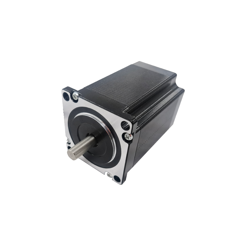
1. Introduction: Deconstructing AC Induction Motor Horsepower The AC Induction Motor is one of the m...
READ MOREIndustry News
2026-10-30
Content
A 57 mm brushless motor quoted at eighteen dollars and another at thirty-one dollars can carry identical nameplate ratings and still behave nothing alike on a test bench. The gap is rarely the copper. It sits in the slot-and-pole combination, the magnet grade, the winding fill factor, the bearing class, and whether the drive runs six-step trapezoidal or sinusoidal field-oriented control. Buyers who compare only frame size and KV usually discover the difference after the first prototype stalls under load.
A brushless motor is a permanent-magnet synchronous machine that moves the magnets to the rotor and the windings to the stator, then hands the switching job that a brush and commutator once performed to power electronics.
Core definition
A brushless motor, also called a brushless DC motor or BLDC motor, is a synchronous electric machine in which rotor position is detected electronically and current is commutated between stator phases by a solid-state inverter. The stator carries the coils, the rotor carries permanent magnets, and torque is produced by the interaction between the rotating stator field and the rotor flux.
The consequences follow directly from that architecture. Removing the brush removes the wear part that limits small brushed tool motors to roughly 500 to 2,000 operating hours, and it removes the carbon dust and commutator arcing that force designers to add EMI filtering. It also relocates the dominant failure mode: in a well-wound brushless motor, bearings and winding insulation set the service life, and a sealed ball-bearing set in a 57 mm frame is commonly rated past 20,000 hours under moderate radial load.
The trade-off is that the motor cannot run without a controller. Two brushless motors with the same KV and the same 24 V bus can therefore behave completely differently at 200 rpm. A six-step trapezoidal drive injects torque ripple at every commutation event, while a sinusoidal field-oriented drive smooths the current waveform and cuts that ripple. When an application needs quiet low-speed motion, the drive choice matters as much as the motor.
A brushless motor typically costs 20 to 40 percent more than a brushed motor of equal mechanical output at low volume, and nearly all of that premium sits in the inverter, the position sensing and the firmware rather than in the motor itself. The magnet wire, laminations and shaft inside a 57 mm brushless frame usually cost less than the electronics that drive them.
Where brushed motors still win is worth stating plainly. In 12 V appliances built in millions of units per year, a 52 mm brushed motor with replaceable carbon brushes can be the correct engineering answer, because duty cycles are short, the load is gentle, and a simple PWM stage costs less than a Hall-effect sensor board. The calculation flips when the machine runs for hours per day, when dust ingress matters, or when the motor sits inside a sealed enclosure where brush debris would be unacceptable.
Six numbers decide almost every brushless sizing outcome: KV, phase resistance, phase inductance, cogging torque, continuous torque at rated temperature rise, and rotor inertia. Everything else on the sheet is context.
Treat published efficiency figures as starting points rather than guarantees. They shift with load point, bus voltage and controller tuning, so dyno the actual motor and drive stack before committing to a production tool.
Cogging torque is the periodic torque ripple a brushless motor produces as its rotor magnets align with the stator slots, and it is the single largest source of audible noise and low-speed position error in direct-drive designs. It is largely designed out at the slot-and-pole stage, long before a prototype exists.
| Slots / poles | Cogging torque | Winding factor | Typical application |
| 12 / 8 | High, 3 to 5 percent of rated torque | 0.866 | Fans, pumps and cost-driven blowers |
| 12 / 10 | Moderate, 1 to 3 percent | 0.933 | Power tools, light traction and general automation |
| 12 / 14 | Low, under 1 percent | 0.966 | Direct-drive robotics and medical handpieces |
| 24 / 22 | Very low, under 0.5 percent | 0.958 | Gimbals, haptics and low-speed positioners |
Cogging is easy to measure before you commit to tooling. Rotate the shaft slowly by hand with no power applied and feel for notchy resistance, or fit a torque sensor and capture peak-to-peak ripple across one full revolution. Slotted stators typically show 1 to 5 percent of rated torque, while slotless and coreless topologies push it below 0.5 percent, which is why they appear in gimbals, haptic actuators and surgical handpieces where a notchy feel is unacceptable.
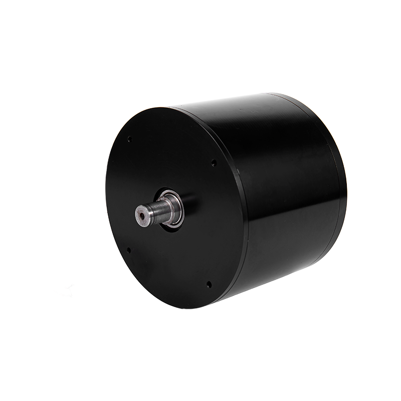 BL112 112mm Low-Cogging Brushless DC Motor 24V 600WWhere cogging matters, this 112 mm brushless motor combines 24 V DC input, 600 W output and a low-cogging design for smooth precision motion.View Product →
Send the complete operating point, not a frame size, because a custom brushless motor is defined by torque, duty cycle, envelope and volume together. A supplier who receives only a diameter and a voltage will quote a catalogue part, and you will spend two prototype rounds discovering the mismatch.
Matching those inputs to a supplier that actually builds the motor is the second half of the job. Jiangsu Retek Motion Co., Ltd., trading as retekmotion.com, is a useful example of the vertically integrated model. The company started in 2012 as a six-person trading operation, brought brushed DC motor manufacturing in-house in 2014, began designing and manufacturing brushless DC motors in 2018, added cable over-moulding and CNC machining in 2021, and moved into an expanded plant in July 2023 while starting coreless DC motor production. By 2024 its motors shipped to more than 20 countries, with standard brushless frames running from 28 mm to 130 mm and an engineering team carrying more than 25 years of motor design experience. When the electronics need to be resolved on the motor side, integrated controller brushless motors are worth specifying early rather than retrofitting later.
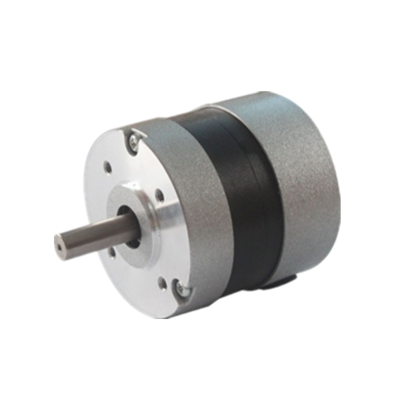 BL57 57mm Brushless DC Motor with High Power DensityIn the 57 mm frame class, this BL57 brushless DC motor suits high-efficiency, long-life use with compact power density and reduced noise.View Product →
Two frames cover a large share of industrial requests. A 57 mm brushless frame suits pumps, blowers and general automation in the 100 W to 400 W class, while an 80 mm frame handles heavier continuous duty where thermal headroom matters more than package size. Both take custom windings, shaft geometry, mounting flanges and connector options, because in this segment the motor is designed around the machine rather than selected from a shelf.
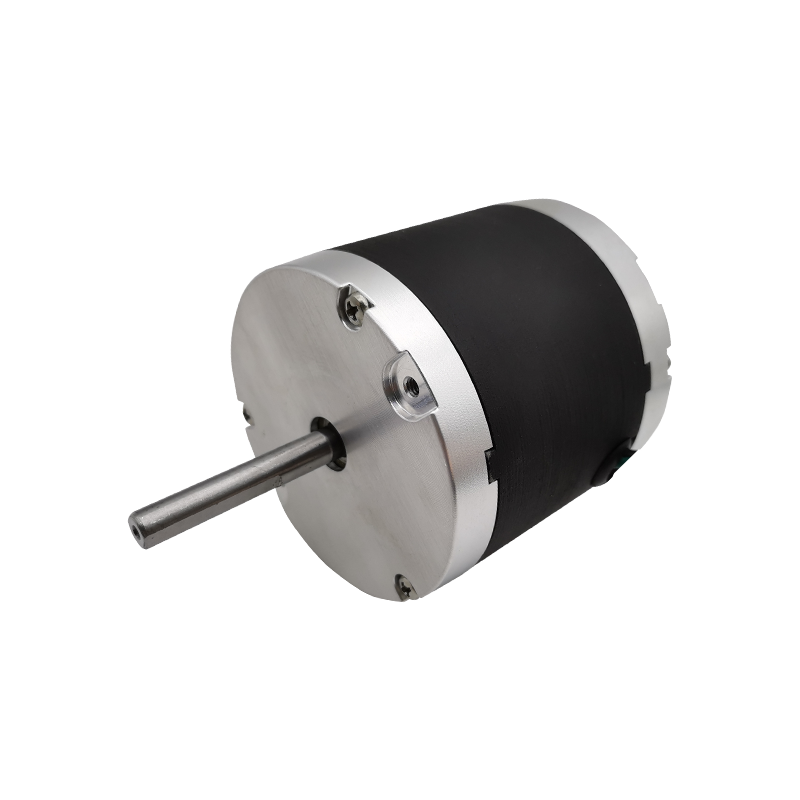 BL80 Series 80mm Brushless DC Motor for High-Load DrivesFor heavier continuous-duty frames, the BL80 series 80 mm brushless DC motor targets high-load, high-torque drives with efficient brushless operation.View Product →
For teams still weighing technology choices, the documented advantages of industrial brushless DC motors over traditional motor technologies give a practical comparison of maintenance intervals, efficiency bands and control complexity before the RFQ goes out.
A brushed motor switches current mechanically through carbon brushes and a commutator, while a brushless motor uses an electronic inverter and rotor position feedback to switch current between stator phases. That removes the wear parts, reduces EMI and raises efficiency, at the cost of a controller and position sensing.
KV is the no-load speed constant, expressed as rpm per volt of applied bus voltage before any load. A 100 KV motor on a 24 V bus spins near 2,400 rpm at no load. KV says nothing about torque or thermal capability, so always size against continuous torque and phase resistance.
Life is set by bearings and winding insulation, not by brushes. A sealed ball-bearing set in a 57 mm frame is typically rated beyond 20,000 hours at moderate radial load, and winding life depends on keeping the hotspot temperature below the insulation class limit.
Yes, and most production brushless motors are. Suppliers adjust winding turns and wire gauge, stack length, magnet grade, shaft geometry, connector type, and gearbox or controller integration. Send torque, duty cycle, envelope, environment and volume data in the RFQ, then expect several sample rounds before release.
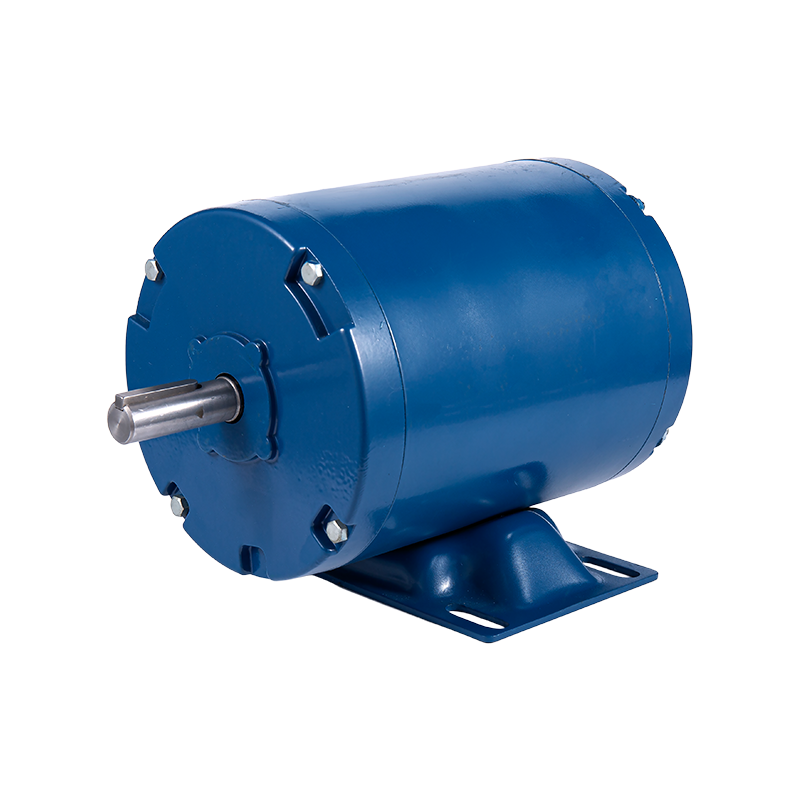
1. Introduction: Deconstructing AC Induction Motor Horsepower The AC Induction Motor is one of the m...
READ MORE1. Introduction In modern industrial automation, data center construction, consumer electronics upgr...
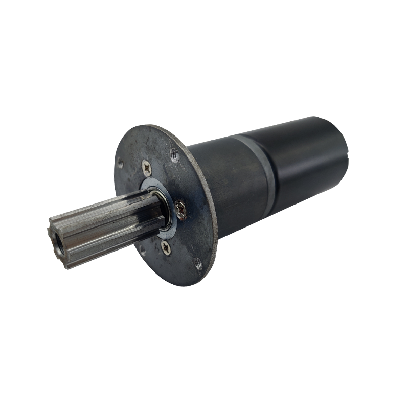
READ MOREStepper motors represent a cornerstone of modern motion control, offering precise positioning and re...
READ MOREThe industrial motor landscape is undergoing a significant transformation, driven by the relentless ...
READ MORERelated Products
Building 10, No.199, Jinfeng Road, Suzhou High-tech, Jiangsu Province, China
+86-133 3869 4967
+86-512 6876 9967
sean@retekmotion.com
rsgrivic@126.com
 WhatsApp
Copyright © Jiangsu Retek Motion Co., Ltd. All Rights Reserved. Custom OEM Industrial Multi Rotor Drone Motors Manufacturers