 Get in touch
 English
 Deutsch
 中文简体
中文简体 Español
1. Introduction: Deconstructing AC Induction Motor Horsepower The AC Induction Motor is one of the m...
READ MOREIndustry News
2026-03-13
Content
Brushless fan motors — and specifically brushless DC (BLDC) fan motors — are the dominant choice for modern cooling and ventilation applications because they outlast brushed motors by a factor of 3–5×, consume significantly less energy, and offer precise electronic speed control. If you are selecting a fan motor for industrial equipment, server cooling, HVAC systems, or consumer electronics, a brushless DC fan motor will almost always deliver a better total cost of ownership than its brushed counterpart. The sections below explain exactly how they work, what the specifications mean, how to compare models, and where each design fits best.
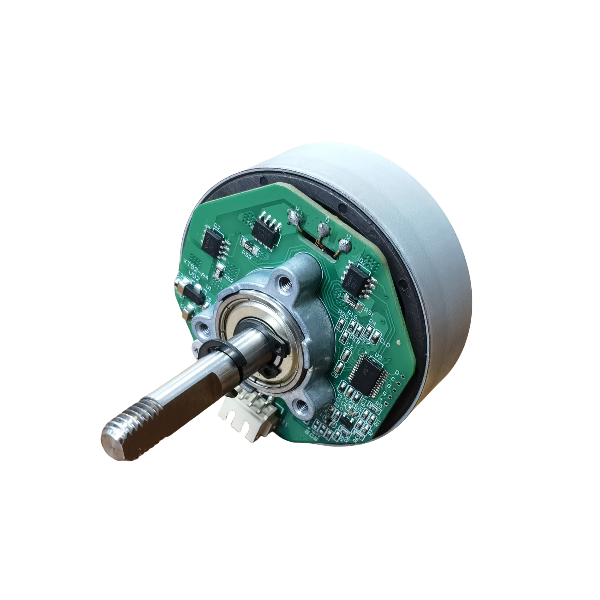
A brushless DC fan motor replaces the mechanical commutator and carbon brushes of a traditional brushed motor with an electronic commutation system. The rotor carries permanent magnets, while the stator holds the wound coils. A built-in or external motor driver — typically using Hall-effect sensors or back-EMF detection — switches current through the stator coils in precise sequence, creating a rotating magnetic field that pulls the permanent-magnet rotor around without any physical contact between moving and stationary parts.
This contactless design is the root cause of nearly every performance advantage a BLDC fan motor offers. Without brushes wearing against a commutator, there is no ongoing mechanical friction loss, no carbon dust contamination, and no spark generation. The result is a motor that runs cooler, quieter, and far longer than a brushed equivalent of the same power rating.
Most fan-specific brushless DC motors use sensorless commutation, detecting rotor position by monitoring back-EMF voltage in the unenergized coil. This reduces component count, lowers cost, and improves reliability in humid or contaminated environments where Hall sensors can fail. Sensored designs — which use physical Hall-effect sensors — are preferred in applications requiring precise low-speed control or immediate startup torque, such as variable-speed industrial blowers that must ramp up from zero RPM under load.
The practical differences between brushless and brushed fan motors go well beyond lifespan. Efficiency, noise, control flexibility, and maintenance requirements all diverge significantly in real-world deployment.
| Parameter | Brushless DC Fan Motor | Brushed DC Fan Motor |
|---|---|---|
| Typical Lifespan | 30,000–70,000+ hours | 5,000–15,000 hours |
| Efficiency | 85–95% | 60–75% |
| Speed Control | PWM / analog / digital (precise) | Voltage variation (less precise) |
| Noise Level | Low (no brush friction/spark) | Higher (mechanical commutation) |
| Maintenance | None (bearing-limited only) | Periodic brush replacement |
| EMI Generation | Minimal | Significant (brush arcing) |
| Unit Cost | Higher upfront | Lower upfront |
| Spark Risk | None | Present (limits use in hazardous areas) |
The efficiency gap is particularly consequential at scale. A data center running 10,000 server cooling fans rated at 15 W each saves approximately 225,000 Wh per day by using 90%-efficient brushless motors instead of 75%-efficient brushed equivalents — a meaningful reduction in both energy cost and heat load that the cooling system itself must then manage.
Reading a BLDC fan motor datasheet confidently requires understanding what each specification actually measures and how it affects suitability for your application.
Brushless DC fan motors are available in nominal voltage ratings of 5 V, 12 V, 24 V, 48 V, and 110/230 V AC (the latter using an integrated AC-to-DC converter). The 12 V and 24 V variants dominate electronics cooling and light industrial applications. A wide input voltage tolerance — for example, 10–30 V DC for a nominally 24 V motor — is a significant advantage in systems where supply rail voltage fluctuates or where the same motor SKU must serve multiple product variants.
Airflow (measured in CFM or m³/h) describes how much air the fan moves in free-air conditions. Static pressure (measured in Pascals or inches of water column) describes the fan's ability to push air through resistance — filters, heat sinks, duct bends, or tight enclosures. High-airflow fans are optimized for open environments; high-static-pressure fans are required wherever system impedance is significant. Always match fan selection to the system impedance curve, not just the free-air airflow number.
The bearing is the primary wear component in a brushless fan motor. The main types are:
Modern brushless DC fan motors support several control interfaces. The most common are:
Brushless DC fan motors span an enormous range of sizes, power levels, and configurations. Matching the motor type to the application requires understanding the dominant constraints of each use case.
| Application | Typical Voltage | Bearing Type | Control Interface | Key Priority |
|---|---|---|---|---|
| Server / data center | 12 V / 48 V | Dual ball / Maglev | PWM + tach | Lifespan, static pressure |
| HVAC / AHU | 230 V AC (EC motor) | Ball bearing | 0–10 V analog | Energy efficiency, airflow |
| Telecom / networking equipment | 48 V DC | Dual ball | PWM + tach + alarm | Reliability, EMI control |
| Medical devices | 12 V / 24 V | FDB or ball | PWM or analog | Low noise, long MTBF |
| Industrial automation / robotics | 24 V / 48 V | Dual ball | RS-485 / Modbus | Vibration resistance, control flexibility |
| Consumer electronics / PC | 12 V | FDB or sleeve | PWM (4-pin) | Acoustic noise, cost |
Electronically commutated (EC) motors are brushless DC motors with an integrated AC-to-DC power supply, allowing them to operate directly from standard AC mains (110–230 V). They are the dominant brushless fan motor technology in commercial HVAC, refrigeration, and data center infrastructure where AC power is the available supply.
EC fan motors typically achieve system efficiencies of 70–80% (motor + drive + impeller) compared to 40–55% for traditional AC induction fan motors at part load. Since HVAC fans spend most of their operating hours at 40–70% of full speed, the part-load efficiency advantage of EC technology translates directly into substantial energy savings. Studies by the Copper Development Association have documented 30–60% energy savings when replacing AC induction fan motors with EC equivalents in air handling units.
Selection follows a logical sequence that starts with thermal requirements and works backward to motor specifications. Skipping steps — particularly the system impedance analysis — is the most common cause of fan underperformance in the field.
While brushless DC fan motors are significantly more reliable than brushed alternatives, they are not immune to failure. Understanding the failure modes helps engineers design systems that maximize operational lifespan.
1. Introduction: Deconstructing AC Induction Motor Horsepower The AC Induction Motor is one of the m...
READ MORE1. Introduction In modern industrial automation, data center construction, consumer electronics upgr...
READ MOREStepper motors represent a cornerstone of modern motion control, offering precise positioning and re...
READ MOREThe industrial motor landscape is undergoing a significant transformation, driven by the relentless ...
READ MORERelated Products
Building 10, No.199, Jinfeng Road, Suzhou High-tech, Jiangsu Province, China
+86-130 1379 7383
+86-512 6876 9967
sean@retekmotion.com
rsgrivic@126.com
 WhatsApp
Copyright © Jiangsu Retek Motion Co., Ltd. All Rights Reserved. Custom OEM Industrial Multi Rotor Drone Motors Manufacturers


