 Get in touch
 English
 Deutsch
 中文简体
中文简体 Español

1. Introduction: Deconstructing AC Induction Motor Horsepower The AC Induction Motor is one of the m...
READ MOREIndustry News
2026-07-06
Content
An AC motor converts electrical energy into rotational mechanical energy using electromagnetism, and understanding how an AC motor works starts with its two core components: a stationary stator wound with electromagnetic coils, and a rotor that spins inside it. When alternating current flows through the stator windings, it generates a rotating magnetic field, and this rotating field is the entire basis of AC motor operation, since it's what induces the rotor to turn rather than any direct electrical connection to the rotor itself in most common designs.
In the most widely used type, the induction motor, the rotor never receives direct current at all. Instead, the rotating magnetic field produced by the stator induces a current in the rotor's conductive bars through electromagnetic induction, and that induced current creates its own magnetic field that interacts with the stator's field, producing torque that drives the rotor to follow the rotating field. The rotor always spins slightly slower than the rotating magnetic field itself, a difference called slip, which is necessary for the induction process to keep working, since a rotor spinning at exactly the same speed as the field would have no relative motion left to induce current.
The number of magnetic poles wound into the stator, combined with the frequency of the AC supply, determines the motor's synchronous speed, which is why standard motors running on 60 Hz power settle into familiar speed classes like 3,600, 1,800, or 1,200 RPM depending on pole count. This relationship between poles, frequency, and speed is fundamental to how an AC motor works and is also why changing a motor's supply frequency, as with a variable frequency drive, is one of the primary ways to control motor speed without changing the physical motor itself.
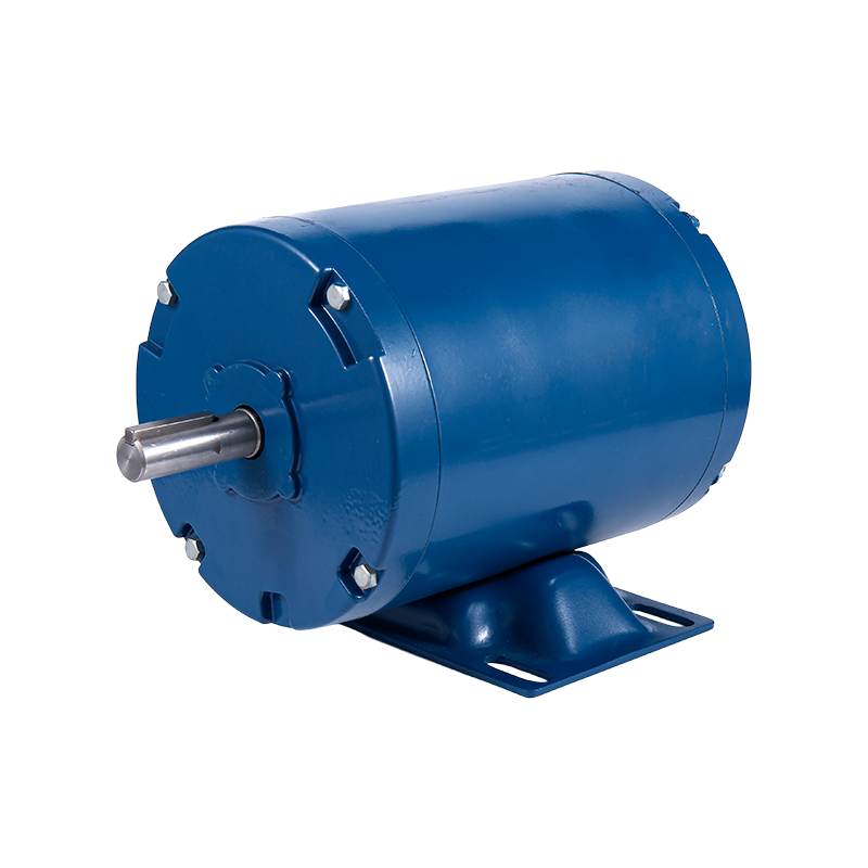
The most reliable way of learning how to find HP of an electric motor already installed and running is to check the nameplate mounted on the motor housing, since horsepower is almost always stamped directly on it alongside voltage, current, and RPM ratings. When a nameplate is missing, damaged, or illegible, horsepower can be calculated from voltage, current, and efficiency using the standard formula: HP equals volts multiplied by amps multiplied by efficiency multiplied by power factor, divided by 746, which converts the resulting wattage figure into horsepower.
For single-phase motors, this calculation only requires the measured line voltage and current along with the motor's efficiency and power factor, both of which are sometimes available from the manufacturer even if the nameplate itself is gone. For three-phase motors, the formula needs an additional multiplication by the square root of three, since three-phase power delivery splits current across three conductors rather than two, and skipping this factor is the most common error when estimating three-phase motor horsepower from electrical readings alone.
When precision matters, such as for sizing replacement equipment or verifying a motor is operating within its rated capacity, measuring actual running current with a clamp meter and comparing it against the calculated or nameplate full-load current gives a much more accurate real-world horsepower estimate than relying on voltage and current alone. A motor drawing significantly less current than its full-load rating is likely running under partial load, meaning the calculated horsepower from raw electrical readings would overstate the motor's actual mechanical output at that moment.
Reversing rotation on a three-phase motor is mechanically simple once the underlying principle is understood: the direction of the stator's rotating magnetic field, and therefore the rotor's direction of rotation, is set entirely by the phase sequence of the three incoming supply lines. Answering how do you reverse a 3-phase motor comes down to swapping any two of the three supply leads at the motor terminals, which reverses the phase sequence and flips the direction of the rotating magnetic field, and by extension, the rotor's rotation.
It's important to swap exactly two leads and no more, since swapping all three, or swapping the same two leads twice, simply restores the original phase sequence and rotation direction rather than reversing it. This is a common mistake for technicians unfamiliar with three-phase wiring, so labeling which two leads were swapped, and confirming rotation direction with a quick test run before full operation, is standard practice to avoid running equipment backward under load.
Before physically reversing any three-phase motor, checking whether the driven equipment, such as a pump, fan, or conveyor, is designed to run in only one direction is essential, since forcing rotation the wrong way on equipment with directional components like impellers or one-way bearings can cause immediate mechanical damage. For motors controlled through a motor starter or variable frequency drive, reversing rotation is often handled electronically through the control wiring or drive programming rather than by physically swapping motor leads, which is generally the safer and more repeatable method in installations where direction needs to be changed regularly.
Single-phase motors don't produce a naturally rotating magnetic field the way three-phase motors do, so they rely on a starting mechanism, typically a start winding paired with a capacitor, to create the initial phase shift needed to establish a rotation direction. This is why the method for how to change rotation of a single-phase motor is fundamentally different from three-phase motors: instead of swapping supply leads, rotation is reversed by swapping the connections to the start winding relative to the run winding, which reverses the phase relationship that determines starting direction.
On most single-phase motors designed for reversibility, this is done through a junction box wiring diagram printed on or near the motor, showing which specific leads to swap for clockwise versus counterclockwise rotation, and following that diagram exactly matters, since single-phase motor wiring conventions aren't standardized across every manufacturer. Attempting to reverse rotation by swapping the main run winding leads instead of the start winding leads generally won't reverse the motor at all, since the run winding isn't what establishes rotational direction in a single-phase design.
Not every single-phase motor is built to be reversible, and shaded-pole motors in particular are typically fixed in one rotation direction by their physical construction rather than their wiring, meaning no amount of lead-swapping will change their rotation. Before attempting to change rotation of a single-phase motor, confirming the motor type, capacitor-start, permanent split capacitor, or shaded-pole, and checking the manufacturer's wiring diagram, avoids wasted troubleshooting time on a motor that simply isn't designed for reversible operation.
1. Introduction: Deconstructing AC Induction Motor Horsepower The AC Induction Motor is one of the m...
READ MORE1. Introduction In modern industrial automation, data center construction, consumer electronics upgr...
READ MOREStepper motors represent a cornerstone of modern motion control, offering precise positioning and re...
READ MOREThe industrial motor landscape is undergoing a significant transformation, driven by the relentless ...
READ MORERelated Products
Building 10, No.199, Jinfeng Road, Suzhou High-tech, Jiangsu Province, China
+86-133 3869 4967
+86-512 6876 9967
sean@retekmotion.com
rsgrivic@126.com
 WhatsApp
Copyright © Jiangsu Retek Motion Co., Ltd. All Rights Reserved. Custom OEM Industrial Multi Rotor Drone Motors Manufacturers